NAFC Test Engine

PCBA + Final Acceptance Testing (USB/Serial & Ethernet)

Automated Test Execution for Production Environments

Configuration-driven test software for PCBA production test and final acceptance testing

From NAFC Tech Solutions — structured automated test systems built for manufacturing

NAFC Test Engine replaces manual, inconsistent test execution and avoids the overhead of custom application development for every product. It provides a controlled operator interface, reusable device integrations, guided workflows, and audit-ready reporting for production environments.

The platform is designed to reduce deployment friction, simplify long-term maintenance, and support regulated manufacturing workflows. Typical projects can materially reduce test time while improving repeatability, traceability, and serviceability on the factory floor.

Use the ROI calculator to estimate labor savings, capacity unlocked, and expected payback based on your own volumes and test times.

Operator-friendly
Prompts, alerts, and instruction dialogs with images, plus a clear pass/fail banner and tones.
Device-flexible
USB/Serial with auto-find, Ethernet/HTTP/raw TCP, and Windows DLL adapters.
Scriptable logic
Math, swaps, cascades, branching, jumps, delays, and inline reports—no programming background needed.
Manufacturing-ready
Log filtering, stop-on-fail, single-step run for troubleshooting, and report generation.

Why this matters on the factory floor

Business impact
  • Reduces manual test effort and shortens cycle time.
  • Improves repeatability across operators, stations, and shifts.
  • Supports cleaner reporting and easier troubleshooting when failures occur.
  • Helps justify automation investments with a clearer ROI case.
Engineering impact
  • Eliminates repeated custom software development for routine test flows.
  • Uses controlled configuration instead of one-off application changes.
  • Supports reusable device profiles for instruments, UUTs, and adapters.
  • Keeps maintenance access controlled while still allowing authorized updates.

Core capabilities

Script table model

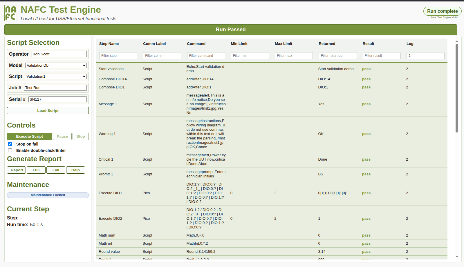
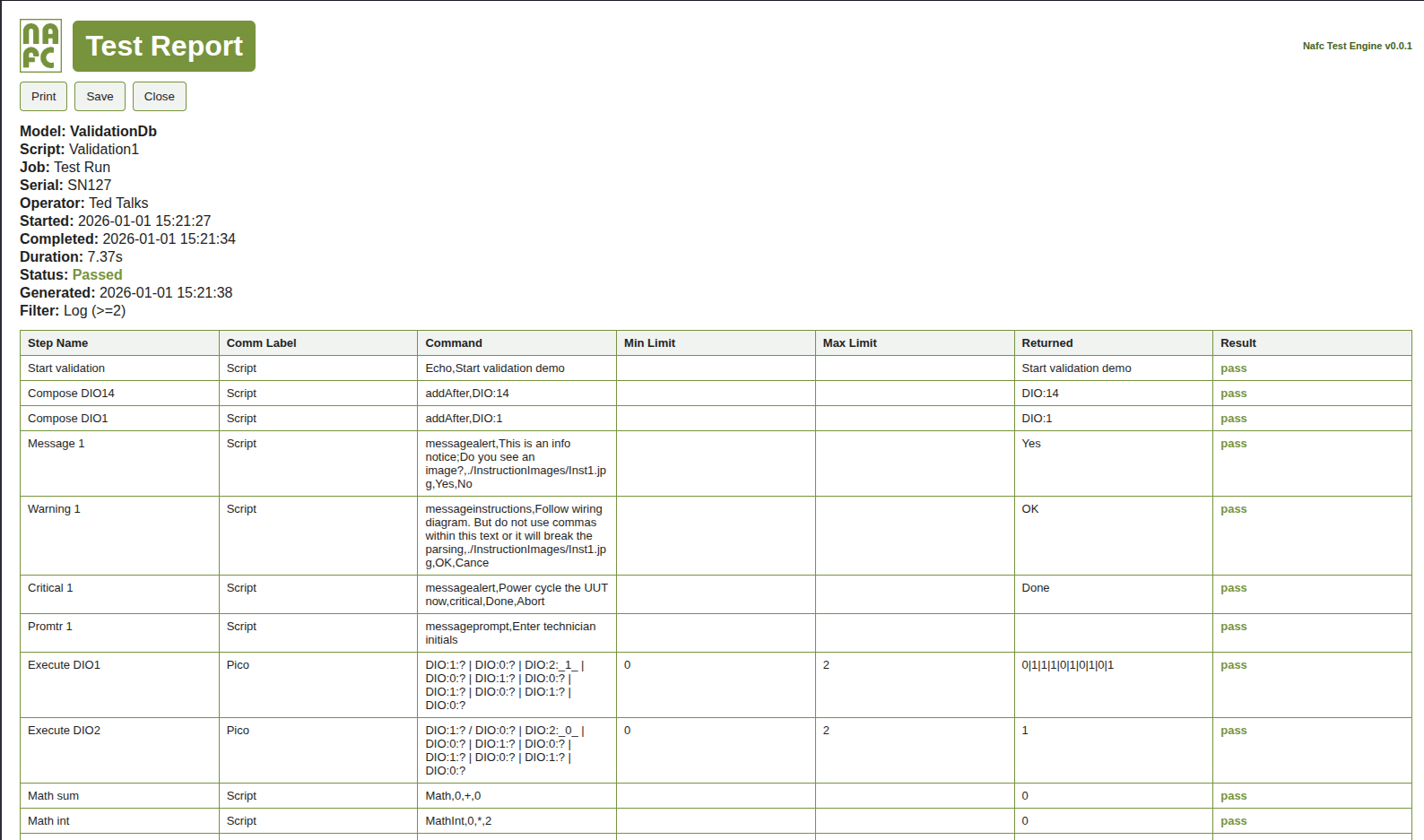
Step Name + Comm Label + Command + Min/Max + Returned + Result + Log. Filters per column; “noop” rows are supported for headers/separators. Log levels drive visibility and report inclusion.

Variable swaps

<Step Name> swaps to Returned values and [Step Name] swaps to pass/fail/aborted results for conditional flow and re-use.

Cascaded commands

Chain commands with | or /; reference earlier cascade results using _index_.

Operator dialogs

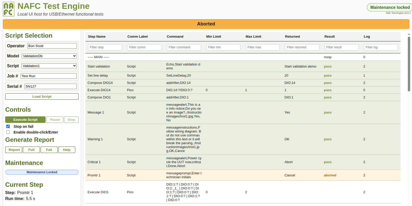
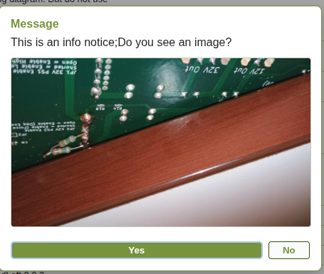
Alerts, prompts, and instruction dialogs with optional images for wiring, setup, and checkpoints. Maintenance lock keeps editing restricted.

Maintenance editing

Unlock to reorder steps, duplicate, delete, drag/drop, and run single steps (troubleshoot mode). Save scripts directly to JSON or SQLite sources.

Device adapters

Serial (COM/USB), Ethernet GET/POST + raw payload, and Windows DLL integration for vendor APIs. Auto-find profiles help bind to the right device.

Device profiles (Comm Labels)
Define a device once using JSON in the Comm Label (protocol, baud/host/port, autoFind), then reference it later by label only (serial or Ethernet). First use provides full details; subsequent steps reuse the label. Case-sensitive (e.g., Pico != pico).
Limits and result evaluation
Returned values are evaluated against Min/Max; numeric values use numeric comparison, otherwise lexicographic. Result is one of: empty / pass / fail / aborted. Optional stop-on-fail halts on the first failing step.
Reports and logging behavior
Log level controls visibility and report inclusion. Reports can be generated as Log/Full/Fail, and overall status locks at EndScript while post-EndScript steps can run for auto-save/print or additional logging.
Steps for setup or control that are not interesting to the operator have the log value of 0. These steps are executed, but not logged or displayed unless a failure occurs.
Steps with a log value of 1 are executed and logged, and like 0, are hidden from the operator.
Steps with a log level of 2 are displayed to the user and included in the default report.

Execution workflow (high level)

Operator flow
  • Select Model / Script, enter Job + Serial, then Run.
  • Engine executes each step: sends commands, captures Returned, evaluates Min/Max, updates Result.
  • Dialogs appear when required (instructions with images, confirmations, prompts).
  • Stop on fail halts on first failing limit if enabled; manual single-step is available in troubleshoot mode.
  • EndScript locks the overall status; post-EndScript actions can continue for logging/reporting.
Backend / dispatch (summary)
  • UI iterates steps and posts execution requests to the backend.
  • Comm Label resolves to protocol adapter: Script / Serial / Ethernet / DLL.
  • Cascaded commands execute in order; _index_ placeholders reuse prior results.
  • Runs are logged (SQLite + JSON), and reports can be generated by filter (Log/Full/Fail).
See the help page for more command reference details (swaps, cascades, device JSON profiles, limits, dialogs, and reports).

Fixtures (PCBA + Final Acceptance)

Legacy fixture wire-heavy
Legacy fixture with dense wiring harness

Observed pain points

  • “Rat’s nest” wiring inside the enclosure: hard to service, fragile connections, noisy signals.
  • Limited strain relief and labeling, so rework and changeovers were slow.
  • Board access is awkward; setup depends on tribal knowledge.
  • Low repeatability between stations and higher false-fail risk.
NAFC fixture (current) robust + serviceable
Current NAFC fixture with clean harnessing and LED indicators

Advantages

  • Internal harnessing is short, labeled, and strain-relieved—no loose bundles, far less noise pickup.
  • Purpose-built internal PCBs replace point-to-point wiring, improving robustness and repeatability.
  • Clear operator indicators (progress bar, status LEDs) and accessible board area for probing.
  • Faster changeover and maintenance; boards and connectors are easy to reach and replace.
Where fixtures fit in the Test Engine
  • Use 
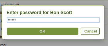
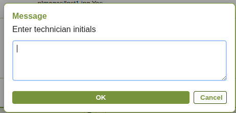
messageinstructions for wiring / setup steps with photos.
  • Use messageprompt for technician initials, workcell, or confirmation inputs.
  • Keep log levels clean: operator-visible steps at Log=2; background steps at Log=0/1.
  • Leverage reusable Comm Labels for instruments/UUTs so scripts stay concise and repeatable.

Next step

Review the ROI calculator to build the business case, or launch the interactive demo to see the operator experience.

Open ROI Calculator Launch Interactive Demo

Screens and operator dialogs

Integration notes (USB, Serial, Ethernet)

USB/Serial / COM devices
  • If the vendor driver exposes a COM port (virtual serial), it works directly via the serial protocol.
  • Use auto-find profiles to locate the correct device by sending an ID command and matching expected text.
  • Use fire: prefix when you need send-only commands with no response wait.
Ethernet devices
  • Supports GET/POST and raw payload styles (host/port in the profile, path in the command).
  • Prefer IPv4 endpoints for consistent resolution behavior.
  • Use standardized step naming and swaps for reusable test blocks.
Contact / Demo

Ready to change how you perform final verification and acceptance testing?
Contact Ali Khajeheian at alik@nafctechsolutions.com or 416-902-0054.